Carrier Rfl 0601el Manual

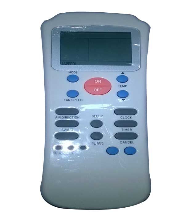
$18.50 Buy It Now 26d 3h, FREE Shipping, Seller: (3,743) 99.7%, Location: Melbourne, VIC, Ships to: AU, Item: 76 Brand New Carrier Replacement Remote Control. This after-market remote replaces the following Carrier remote models: RFL-0601E, RFL-0601EH, RFL-0601EL.
Carrier Rfl-0601ehl User Manual For Carrier RFL-0601EHL RFL-0601NEHL RLF-0301E 36KCARMS AC Air Conditioner Remote Control ----- Where to see the latest. Get free help, tips & support from top experts on manual carrier 36kcarms related I lost the user´s manual of my wireless remote control model RFL-0601EHL.
To check which model your remote is, check the back of the remote. If you have lost the remote you can also check your user manual.
Not all remotes work all models - please select the right remote for your air conditioner. We offer regular postage and express post options. Items are sent in a padded bag and posted from Melbourne via Australia Post each weekday and on Sundays so you get your item quickly.
Condition: Brand New, Brand: Unbranded, Model: RFL-0601E, RFL-0601EH, RFL-0601EL, MPN: RFL-0601E, RFL-0601EH, RFL-0601EL See More.
• Control Module Communication.4 Carrier Comfort Network Interface.4 OPERATING DATA. • CONTENTS (cont) • LEAD/LAG DETERMINATION • CAPACITY SEQUENCE DETERMINATION • CAPACITY CONTROL OVERRIDES Head Pressure Control.27 •.
• Information is transmitted between modules via a 3-wire com- UNIT 30GTN,R munication bus or LEN (Local Equipment Network). The — — CCN (Carrier Comfort Network) bus is also supported. Con- — nections to both LEN and CCN buses are made at TB3.
• YELLOW LED — The MBB has one yellow LED. The Carrier Comfort Network (CCN) LED will blink during times of network communication. Carrier Comfort Network (CCN) Interface — The 30GTN,R chiller units can be connected to the CCN if desired. • CR-A1 CR-A1 CR-A1 LEGEND FOR FIG.
1-4 — Compressor Contactor — Circuit Breaker — Carrier Comfort Network — Compressor Ground Fault — Cooler Heater Thermostat — Circuit — Cooler Heater Relay — Compressor Protection and Control System — Chilled Water Flow Switch —. • DATA COMMUNICATION PORT Fig.
2 — 24 V Control Schematic, Unit Sizes 040-070. • DATA COMMUNICATION PORT Fig. 3 — 24 V Control Schematic, Unit Sizes 080-110, 230B-315B Fig. 3 — 24 V Control Schematic, Unit Sizes 080-110, 230B-315B. • DATA COMMUNICATION PORT Fig. 4 — 24 V Control Schematic, Unit Sizes 130-210, 230A-315A, 330A/B-420A/B. • LEN (LOCAL EQUIPMENT NETWORK) CEPL130346-01 STATUS Fig.
Research methodology by cr kothari pdf. 6 — Enable/Off/Remote Contact Switch, Emergency On/Off Switch, YELLOW LED - CCN (CARRIER COMFORT NETWORK) Fig. 5 — Main Base Board RESET BUTTON (SIZES 130-210 AND ASSOCIATED MODULES ONLY) and Reset Button Locations. • OPERATING DATA Sensors — The electronic control uses 4 to 10 thermistors to sense temperatures for controlling chiller operation. These sensors are outlined below. 7-10 for thermistor locations.
Thermistors T1-T9 are 5 kΩ at 77 F (25 C). • 040-070 080-110 AND ASSOCIATED MODULAR UNITS* 130-210 AND ASSOCIATED MODULAR UNITS* *When thermistor is viewed from perspective where the compressor is on the left and the cooler is on the right.
8 — Thermistor T3 and T4 Locations. • LEGEND EXV — Electronic Expansion Valve Fig. 9 — Compressor Thermistor Locations (T7 and T8) Fig. 10 — Typical Thermistor Location (30GTN,R and 30GUN,R 210, 315A, 390A, 420A/B Shown) • The space temperature sensor includes a terminal block (SEN) and a RJ11 female con- nector. The RJ11 connector is used to tap into the Carrier Com- fort Network (CCN) at the sensor. To connect the space temperature sensor (Fig. • Thermostatic Expansion Valves (TXV) — 30GTN,R and 30GUN,R 040-110 units are available from the factory with conventional TXVs with liquid line solenoids.
- воскресенье 17 марта
- 57